For DCC and Motorola II
Switches auxiliary functions like horn, whistle, light and smoke.
Features
Multi-protocol function decoder for DCC and Motorola II
Suitable for the new DCC protocol for Function decoders, with up to 32000 special functions
4 Function output with up to 0.6A capacity
All outputs can be individually configured for:
- direction independent outputs
- delayed outputs
- blinking outputs
The outputs, when used in pairs, can be dimmed using PWM
Programming with a DCC or Motorola Digital centre
In DCC operation can be programmed by Register, CV or Page programming
Description
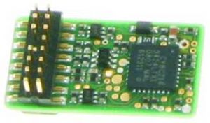
The function decoder 73 900 is a small efficient Multi-protocol decoder. It can be used with DCC
and Motorola-II Digital systems. The decoder cannot be used as a function decoder with the old
Motorola data format.
The function decoder has 4 outputs with a load capacity of up to 0.6A each. For smaller loads
with voltage lower than 20V the output can be reduced when using the outputs in pairs (A1 and
A2 as well as A3 and A4).
The outputs can be configured individually. Each output can be activated for only one travel
direction. It can be programmed to switch on after a set time or switched on and off by a blink
generator.
In analog operation you can determine which outputs are to be switched on. Direction
dependent outputs are toggled by the DC power on the track.
In the factory default state, the decoder automatically recognizes the DCC and Motorola data
formats as well as analog operation. The operation type can also be set up manually.
Installation of the Function decoder 73 900
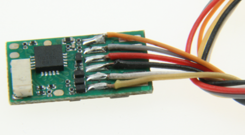
Connecting the wires
When the decoder is installed in a vehicle, the black
wire is connected to the left wheel pickup (2-rail) or to
the vehicle chassis (3-rail). The red wire is connected
to the right wheel pickup (2-rail) or to the vehicles third
rail pickup (3-rail).
The loads are soldered directly to the circuit board of
the decoder. As you can see in the diagram one side
of each load is connected to a function output and the
other side to either the black wire (vehicle chassis) or
the solder pad for 20V return.
73 900
Fastening the decoder in the Vehicle
Use the double sided adhesive pad provided to fix the decoder to the desired location in the
locomotive. The adhesive pad protects the decoder from contacting conducting surfaces and
holds it in place.
Start-up
Double check the correct installation with a continuity tester or an Ohmmeter.
When placing the device make sure it does not come in contact with any conducting surfaces in
the vehicle. Also ensure that a short circuit cannot occur when the locomotive is close and that
the wire is not cinched.
Digital operation
Allocation of the special functions to the switching outputs via CV35 to 42
In each case 2 CVs serve to allocate a function to an output. All functions from 0 (light) to
32767 can be used (Motorola: 0-4, DCC: 0-32767). CVs 35, 37, 39 and 41 contain the high
order byte and the CVs 36, 38, 40 and 42 the low order byte of the function code.
Calculation: Function number = high order byte x 256 + low order byte
If an output is to be switched by Functions 0-28, the high order byte must have the value of 128.
Example 1: Special function f12 is to switch output A1.
CV35 = 128 (factory setting)
CV36 = 12
For higher Functions the high order byte receives the appropriate CV.
Example 2: Special function 2000 is to switch output A1.
Divide the address value by 256 (2000/256 = 7 remainder 208).
Enter the result (7) into CV35.
Enter the remainder value (208) into CV36.
For Experts: The decoder controls all functions which are defined in the newest version of the
NMRA DCC standard. Only the CVs 35 to 42 deviate from the NMRA DCC standard.
There are the functions 0-28, as well as two further possible switching functions, for transfer to
a vehicle decoder which is marked with Binary State control (BSC). If CVs 35, 37, 39 or 41
(High byte) are given a value of 128 then the matching outputs of the decoder are controlled by
the DCC special function commands (0-28). If CVs 35, 37, 39 or 41 have a value smaller than
128 the matching output of the decoder is controlled via BSC and function numbers 0-32767
can be used. In this case (CVs 35, 37, 39 or 41 = 0) the outputs are also controlled via BSC if
function numbers 0-28 are used.
Direction dependent Outputs
In CVs 52 and 53 you can specify if the state of an output is to depend on the travel direction or
not. If the Bit for the respective output is set to 1 the output matching this CV direction
sensing is turned off. CV52 is for the forward direction and CV53 is for the reverse direction,
Delayed Outputs
In CV54 you can specify if an output activation is to be delayed or not. If the Bit for the
respective output is set to 1 the output will be switch with a delay. The delay can be specified
in CV55 in 0.5sec intervals. This delay is common to all outputs activated in CV54.
Blinking Outputs
In CV56 you can specify if an output that is switched on is to operate on a blinking cycle or not
e.g. for a blinking light. If the Bit for the respective output is set to 1 then it will blink. CV57
contains the time constants of the blinking cycle. A value of 1 means the output will blink 10
times per second. A value of 10 means the output will blink on and off once per second. The
time constants apply to all outputs that are set to blinking type in CV56.
A short circuit with the Motor, lighting, third rail pickup and wheels can destroy the
device and eventually the locomotives Electronics!
Analog operation
For analog operation CV13 determines which outputs are switched on. Outputs that are
programmed to be direction dependent in CV52 and CV53 will be switched independently of the
direction in DC analog operation.
Programming
Note: So that the decoder can be read on a DCC programming track a load must be connected
to output A1.
Configurations variables (CVs) form the basis of all programmable settings of the decoder in
accordance with the DCC standard. The decoder can be programmed with the Intellibox, DCC
centres and Motorola centres.
Programming with the Intellibox
Irrespective of the format to be driven later we recommend that the decoder be programmed via
the programming menu for DCC decoders.
The Intellibox supports DCC programming with a simple input menu. Long addresses do not
have to be laboriously calculated, they can be entered directly. The Intellibox automatically
calculates the values for CV17 and CV18.
For the exact process please read the appropriate chapter in the Intellibox manual.
Special case decoder addresses 80 to 255 in the Motorola data format
The Intellibox supports an address range up to 255 in the Motorola data format. Addresses 1 to
80 can also be programmed (problem free) using DCC Programming. If, however, an address
above 80 is to be used it must always be programmed as outlined in the chapter Programming
with a Märklin Centre.
After this programming is complete, the CV1 will contain a value of 0 and the decoder will
respond to a Motorola address above 80.
Programming with DCC devices
Use the programming menu in your DCC Centre to program the decoder CVs in either register,
direct CV, or page programming mode. It is also possible to program the decoder on the main
line using a DCC Centre.
Refer to the manual of your control centre for full instructions on the process.
Programming of long Addresses without the Programming Menu
For programming with a centre which does not support programming with an input menu, the
value for CV17 and CV18 must be calculated. Here is an example for programming the address
2000.
Divide the addresses by 256 (2000:256 = 7 remainder 208).
Take the result (7) and add it to 192.
Program this value (199) into CV17.
Program the remainder (208) into CV18.
Important: Set Bit 5 of CV 29 to 1, so the decoder uses the long address.
Calculating the CV value
If several different settings on the decoder are to be changed in a particular CV, the value which
is to be entered is calculated using the CV table, and the values of the desired functions are
simply added.
Example: Outputs A1 and A4 are to blink.
OutputA1 blinks Value = 1
OutputA2 does not blink Value = 0
OutputA3 does not blink Value = 0
OutputA4 blinks Value = 8
The total value is 9.
This value is programmed into CV56.
.jpg)
.jpg)
.jpg)
.jpg)