The LoDi Rektor
1. The LoDi rector and its connections
The LoDi rector is an interface that is required to generate the necessary locomotive data formats.
At the moment the LoDi Rector supports DCC, M3 and Motorola in all variants.
The only limit here is the model railway control software. It is connected via a modern, future-oriented and driverless interface.
It is therefore completely independent of the installed operating system.
However, you should have the latest Java version installed.
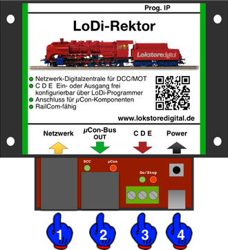
Regarding the connections on the LoDi rector:
2. LEDs and buttons of the LoDi rector

The LoDi Rector has several LEDs and buttons that should help you to recognize the status of the device and to quickly understand faults.
3. Connection of the power pack to the LoDi rector

We deliver the LoDi rector with a high-quality USB power supply. Of course, you are also welcome to use your own USB power supply unit, but this should provide at least 1 ampere.
4. The LoDi Rector Connection to the network

Our devices all work with a modern network interface.
This offers you a lot of advantages when handling the devices. With the help of this network interface, you can easily integrate several interfaces into your system.
There are almost no limits to your imagination here.
You can use this technology to implement large to very large systems, but small systems also benefit from this technology.
Thanks to network technology, it is no longer a problem to control your system with your laptop or tablet. Today's W-Lan routers are absolutely capable of transmitting these connections quickly enough.
When integrating the LoDi interface into your network, there is little to consider.
However, it is always easier to integrate the LoDi interface into an existing network than to install another network card in the computer.
If you need help with the integration, please feel free to contact us using the contact form ,
or you can contact our users in the forum , who will be happy to help you.
As you can see in the picture above, we pay a lot of attention to the color typology of the network cables.
Yellow is the international standard for computer networks.
You are of course welcome to use other colors, but we adhere to these standards.
In the example shown, you can now see that the computer is connected to a switch or router.
Of course, you can also connect the computer via W-Lan.
The LoDi Shift Commander is also connected to the switch or router.
The cable going to the left could be your internet line or other devices connected to your network.
If the ports on the switch or router are not enough for you, you can simply connect a new switch to the existing switch. The switch's link channels automatically route the data to the right device, all you have to do is connect the cables.
But please make sure that you don't build a loop, a loop would be a circle, so to speak, with which you paralyze your network.
Once you have connected the LoDi interface correctly, you can configure the network address
(the so-called IP address) via our LoDi ProgrammerFX .
5. The LoDi rector Connection to the LoDi bus
The LoDi rector has the LoDi bus, formerly the µCon bus. This was originally developed as a pure booster bus for the µCon system of the time. As a LoDi bus, the bus was and is constantly being further developed and maintained.
The LoDi bus offers many advantages, especially for the boosters, because we can use the LoDi bus to implement long network cable lengths, lengths of up to 1500 meters are possible.
Boosters have the same signal at every point, there is no time offset in the track log.
The LoDi bus is the perfect choice, especially for large installations.
In addition, we get a lot of information via the LoDi bus, such as:
- Power consumption of the individual outputs on the booster
- booster status
- voltage indicator
- temperature monitoring
- Free addressing of the connected LoDi bus components

Here you can see the connection of a LoDi booster to the LoDi rector. The LoDi bus requires a termination plug, which is included with every LoDi rector.


Our system is fully compatible with other LoDi bus components. The LoDi rector automatically recognizes the connected components, whether it is a LoDi booster , µCon booster or Railspeed.


The Railspeed from LSdigital can be fully operated on the LoDi rector. It doesn't matter where in the bus it is attached.

6. Conventional boosters on the LoDi Rector
If you have boosters and are satisfied with them and only want to connect the LoDi rector as a control center or generator, you are of course welcome to do so.
In the past, customers have also repeatedly asked us what they should do with their old boosters.
We say, join them!
Maybe you still have a track that is not integrated into the layout, or you want to switch points and signals via DCC, M3 or Motorola. The possibilities are all there.


If the connected booster now reports a short circuit to E, this will be displayed in our tool.
7. LoDi rector as a booster interface via CDE or Sniffer-IN
The LoDi rector can be used as a control center, generator or booster interface.
What does a booster interface mean?
Many model railway controls support the possibility of recognizing where there is a short circuit. There are possibilities here to give an impulse to the model railway control software via feedback modules that the specific booster circuit has a short circuit.
The LoDi Rector itself, on the other hand, collects the data from the boosters and then sends them to the model railway software.
Here you can now evaluate more data:
- Individual boosters are displayed with their address
- Power consumption and voltage can be displayed
- temperature of the boosters
- Booster status On/Off short circuit
The LoDi rector has a switchable CDE input or output. You yourself can use the
LoDi programmers determine how the output is configured. To configure the CD E port, click here .

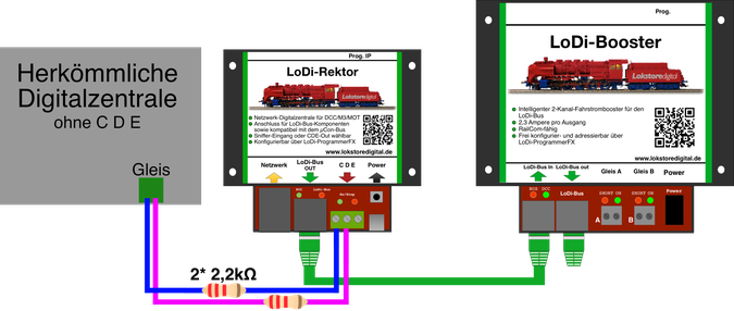
Here you can see the connection of a conventional digital command station from Lenz with a CD E output. However, you should only connect C and D. If E is also connected, the LoDi rector also forwards a short circuit to the control center, which then sets the entire track current to stop again.
All digital command stations with a CD E output can be connected to the LoDi rector! ! !

The CD(E) cable should not be longer than 2 meters!
The Rector also only provides 5 volts at the CDE output, but there are boosters that require a higher CDE voltage to be able to run.
8. LoDi rector as a booster interface via conventional central units
The market is full of digital centers, as a customer you really don't have a big overview here. In principle, all command stations do one thing in the same way, they should take over the control of your trains and/or switches. There are all variants of digital command stations, from high-end to small USB sticks.
However, there are actually command stations on the market that do not have a CD E connection.
Do they have to stay outside?
NO! Any command station can be connected to the LoDi rector, it only has to speak DCC or Motorola.
Of course, the question arises, why should a digital command station be connected to the LoDi rector if he is one himself? Quite simply, you know your system and are happy with it, but you would like to have the advantages of RailCom and a booster logic.
Perhaps you have become so used to your hand controller that you don't want to do without it.
Each digital center has a track output to which you can connect your track.
It is of course not possible to connect the track output directly to the LoDi rector.
To do this, 2 resistors, each with 2.2kΩ, must be inserted in the line, as can be seen in the picture below.
This means that almost all control centers can be connected to the LoDi rector.
9. Specifications
Dimensions:
Length 8.9cm
Width 10cm
Height 3.5cm
Weight:
89 grams
The USB-C connection can be supplied with all common USB-C cables or power supplies.
The maximum load of the USB power supply can be up to 3 amps.
10. Setting up the LoDi rector in the LoDi ProgrammerFX
