The LoDi-8-GBM v2
The LoDi-8-GBM v2
Update late 2022:
Our LoDi-8-GBM also gets a small update, the LoDi-8-GBM v2. It can now be fully updated and prepared for the DCC-A.
We introduce:
Our new track occupancy reporting module - the second component of our new feedback system, which has already proven itself very successfully in small and large to very large systems. The focus here is on the simplicity of setup and monitoring options.
With the new S88.2 standard and the unconditional RailCom compatibility, we offer a new dimension of safety and where there was only hope before, we now have reliable knowledge of where the vehicles are actually located on the layout.
The properties of the LoDi-8-GBM v2
- The LoDi-8-GBM v2 is a track occupancy detector developed for the S88.2 bus.
- It serves 8 track sections, each of which can be loaded with 3 amps.
- All 8 track sections, i.e. reporting channels, are RailCom-capable and can be monitored via channels 1 and 2.
(With Channel 2, a maximum of 8 locomotives can be recognized in the message channel.) - The track occupancy detector also provides an exact power consumption per track section and can even detect short circuits directly in the block.
- Can be used universally with 2- and 3-rail track systems.
- The LoDi-8-GBM v2 can easily be configured via the LoDi-ProgrammerFX .
- Display for direct control of the detectors and display of the module address.
- Fully backward compatible. The LoDi-8-GBM v2 can also be operated on the s88N and with an adapter on an old s88 bus. However, the full functions are not available here as in the S88.2 bus.
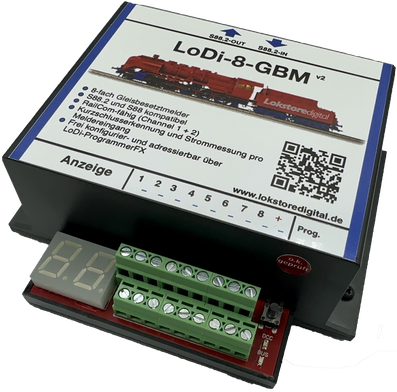
1. The LoDi-8-GBM v2 and its connectors
Regarding the connections on the LoDi-8-GBM v2:

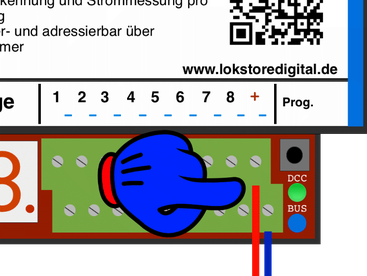
2. The LoDi-8-GBM v2 and its LEDs

3. Connection of the LoDi-8-GBM v2 to the S88.2 bus
As already mentioned several times, the LoDi-8-GBM v2 has the new S88.2 bus. This is provided by the
LoDi S88 Commander FX . You can connect up to 96 LoDi-8-GBM v2 to one
LoDi-S88-Commander FX.
If the module is operated on an S88.2 bus, the following features are available:
- Occupancy notification of the individual blocks with display
- Short-circuit detection of the individual blocks. This is done via another register, which means: If a short circuit is detected on output 1.1, for example, 1.9 is reported as being occupied. The short circuit can already be displayed on every model railway control system.
- Current measurements per signaling channel, with a display option in the software.
- Setting the short circuits per signaling channel.
- Setting of the current detection threshold per signaling channel
- RailCom recognition of channels 1 and 2 per message channel (max. 8 locomotives per message channel).
- Freely addressable, now the module keeps its address, there are no more shifts!

4. Connection of the LoDi-8-GBM v2 to the s88 and s88N bus
The LoDi-8-GBM v2 is equipped with the new S88.2 bus, which does not mean, however, that the module cannot also be operated on conventional control panels with s88 or s88N.
These functions are available to you when operating on the old s88 bus:
- Occupancy notification of the individual blocks with display
- Short-circuit detection of the individual blocks, here via an additional register, which means:
If a short-circuit is detected on output 1.1, for example, 1.9 is reported as being occupied. The short circuit can already be displayed on every model railway control system.

Here you can see the connection of a LoDi-8-GBM v2v to a µCon-s88 master. It doesn't matter whether the LoDi-8 GBMs are connected to bus 1, 2 or 3, they behave like normal s88 modules.


Here you can see the connection of a LoDi-8-GBM v2 to an LDT-HSI. Of course, any kind of
s88N modules can be hung in between.


It is possible to connect the LoDi-8-GBM v2 to a conventional digital command station. To use the devices on an older control panel without the s88N connector, you need an adapter.
We offer the LoDi S88 adapter for this purpose, which can be used universally

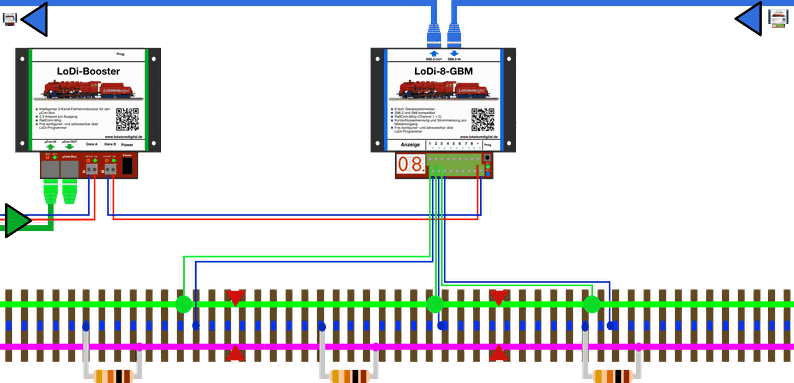
5. Connection of the LoDi-8-GBM v2 booster voltage
The LoDi-8-GBM v2 features a booster input terminal. You have to connect a booster or a conventional digital center to this.

In the first example you can see the LoDi Booster powering the LoDi-8-GBM v2.
Please make sure that the red wire. i.e. the + connection is connected to the respective right booster terminal at output A and B. If the red cable is on the other side, this can affect the RailCom signal.
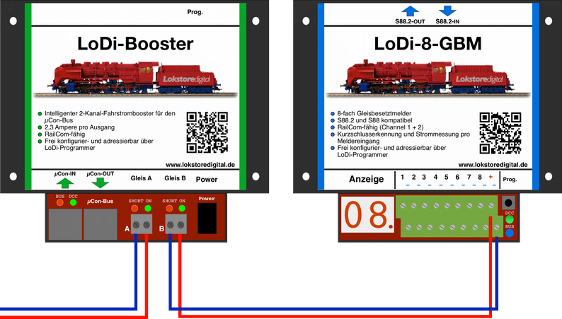

A complete representation, in which the buses of the modules are also shown.


Your wiring could look like this, for example. Of course, you can also have several signaling modules supplied by one booster section.

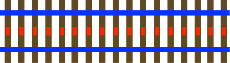
6. Connection of the LoDi-8-GBM v2 to the 2-rail track
An occupancy report for the 2-rail track is easy to implement with the LoDi-8-GBM v2, always depending on how many feedback sections you need for your model railway control.
In our diagram, we are now assuming one detector per block; of course, entry and brake detectors could also be required or wanted. If you are interested in our cable drives that we use click here under " Useful Info "

7. Connection of the LoDi-8-GBM v2 to the 3-rail track
The 3-rail system is very common among model railroaders. This is exactly why the 3-wire driver is important to us. With the LoDi-8-GBM v2 it is possible to run MFX® and DCC on one track.
What advantages does this bring?
- Feedback or block exact position of the vehicles
- You place a locomotive on the track, the computer recognizes it and automatically inserts the locomotive into the block.
- Monitoring of the switch route
- Short-circuit report feedback exact
- Power consumption feedback exact
The locomotive only needs a RailCom transmitter for this. If you already have another decoder installed in the locomotive that can do DCC, you can run it directly in DCC.
Most decoders on the market support RailCom.
Another note:
Motorola has to stay out of this. If you don't want to do without Motorola, you have to use the conventional solution with the ground message.
For this we have developed the LoDi-RM-16+ , which even offers a ground return to the track (diode trick).
Please note, however, that no specific locomotive message can be evaluated with this variant of the LoDi-RM-16+ .
If you have any questions, please do not hesitate to contact us.

First of all, let's look at the wiring of the 3-wire system.
A little rethinking is required here, which we will briefly explain to you here: (Similar explanation under LoDi Booster Section 7)
Imagine the center conductor simply becomes ground. Since the ground on the track can always be one, you don't have to separate the new ground either.
Which means the center conductor is always connected together.
If you have already disconnected the center conductor on an existing layout, it can be reconnected or you can run the booster sections with ground isolation.
Here is the normal standard procedure used with 3-wire.
Center conductor RED is B, ground track above and below BLUE is O
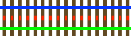
In this example you can see that the upper side carries the mass, here BLUE so O.
The center conductor remains RED i.e. B.
The bottom side of the track is now the feedback for the ground message, i.e. GREEN , as has been usual for the message in the 3-wire process

So that the Railcom data from the locomotive block-specifically arrives at the model railway software, we have to conduct the current via the LoDi-8-GBM, which is used for this application in the 3-wire process.
It takes a little rethinking, but we know from numerous customers that this solution works perfectly.

An occupancy report for the 3-rail track is easy to implement with the LoDi-8-GBM v2, always depending on how many feedback sections you need for your model railway control.
In our diagram, we are now assuming one detector per block; of course, entry and brake detectors could also be required or wanted. If you are interested in our cable colors used, click here under " Useful Info "

Here we have separated the track on the right and left and leave the middle conductor connected. In this variant, the shackles do not have to be separated on the C track, for example. In this variant, however, only power consumers are recognized, which means only locomotives or wagons with a pick-up shoe.

Another variant is the wagon report. This means as soon as you park a car in a feedback area, a message will be generated. To do this, however, we have to separate the connection from the left to the right rail, as with C Track.
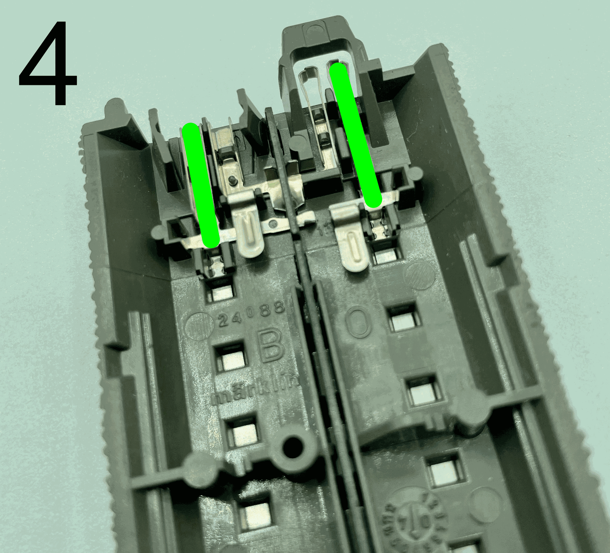
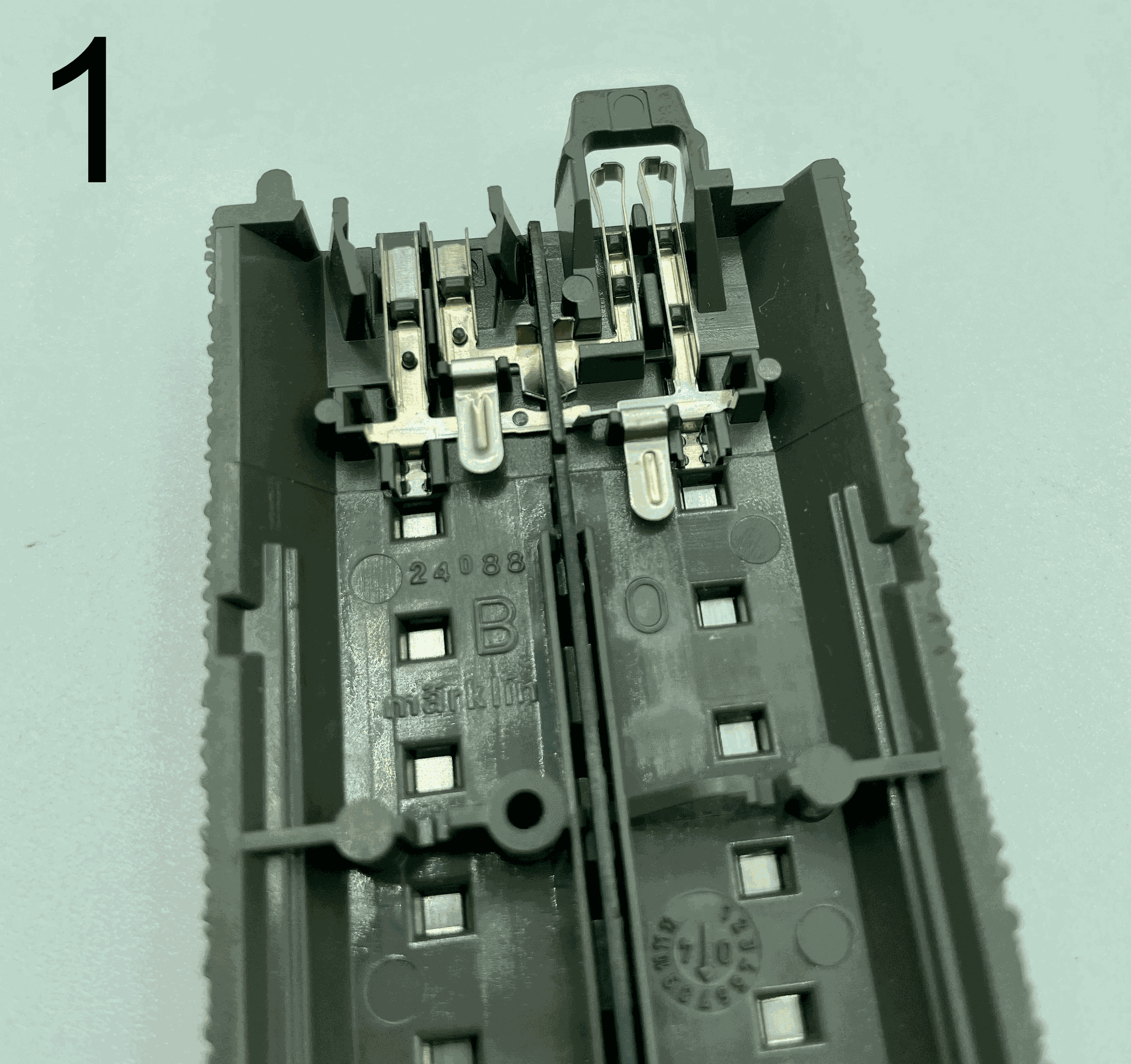


On pictures 1 and 2 you can see the connection in the C track, through which contact is made from the right to the left side on the underside of the track.
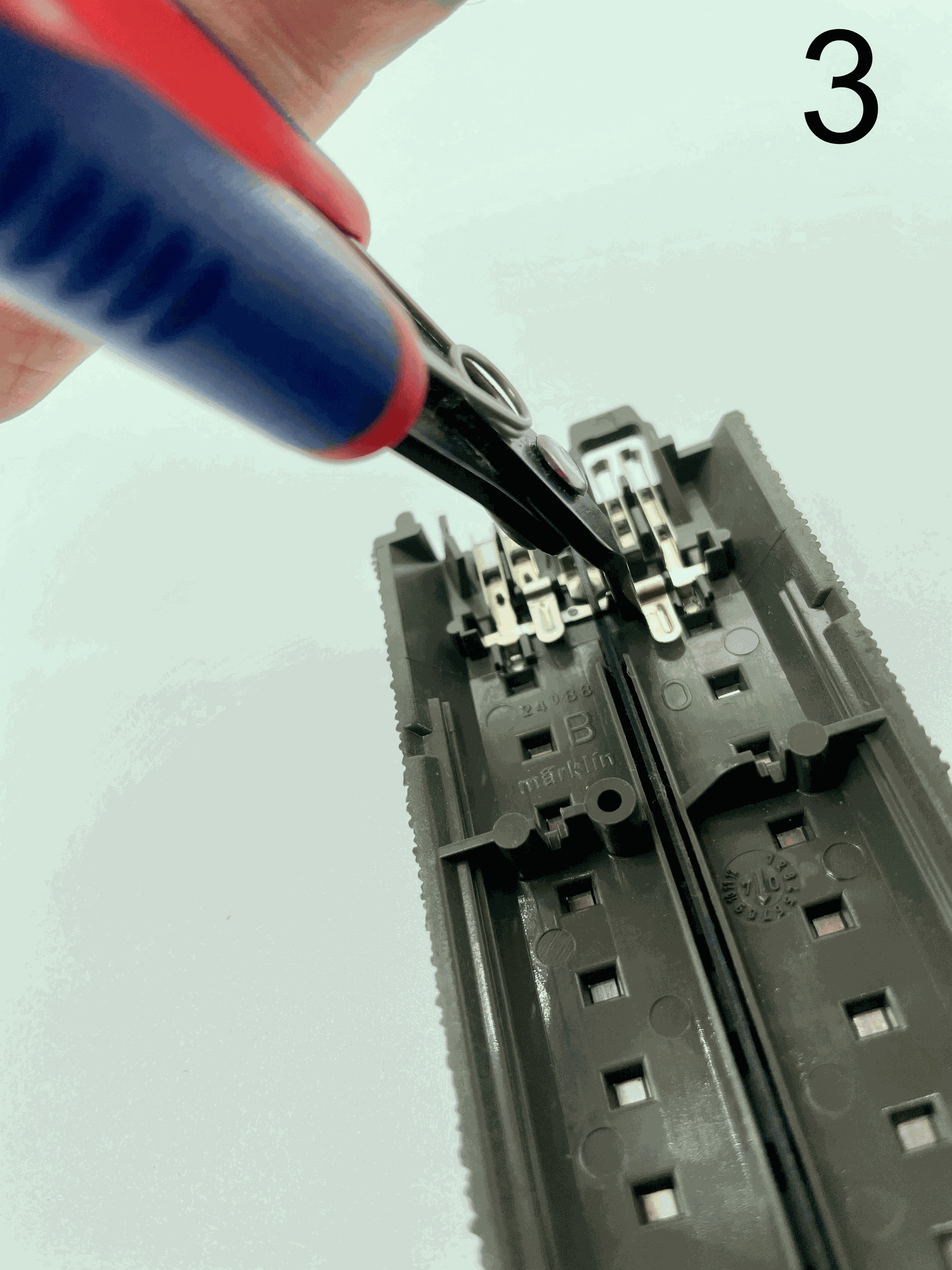
In picture 3 we now put a small side cutter on the right flap 0. The connection can now be broken there.
In picture 4 you can see that the connection is broken. When separating, note that both sides must be separated from the track. It is also advisable to have a voltmeter in the house for this purpose. The continuity checker can show you that the right side is really separated from the left side.
Both sills are still isolated in one block, but now a resistance of 10 kilo ohms is installed between the middle conductor, i.e. the ground (blue), to the not-current-carrying sill purple.

Here you can see another example image in which a long, single-track section has been subdivided with several blocks or sensors. A resistor is now installed in each section.
The points are not separated, they are simply wired as shown in the diagram above.
Switches are not separated, in principle this can be done with some effort, but we advise against it.
8. Specifications
Dimensions:
Length 130cm
Width 115cm
Height 4.5cm
Weight: 169 grams
The feedback can be supplied from 12 to 24 volts at the digital terminal.
! Pay attention to the information provided by the manufacturer of your digital command station or booster!
Loadable by consumers with short-term 5 amps and permanent 3 amps per output.
Suitable for all common track sizes.
9. Setting up the LoDi-8-GBM v2 in the LoDi programmer

Can this be used to trigger turnouts or other actions as it appears some other feedbacks do?